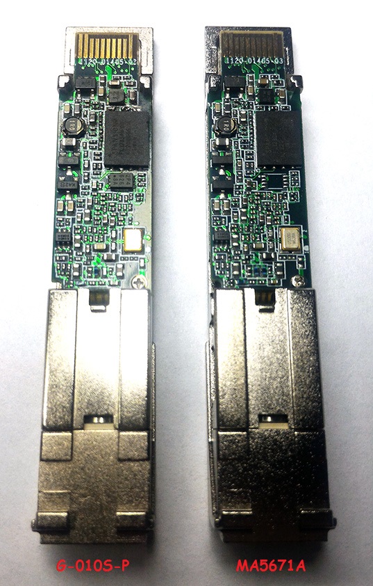
Huawei MA5671A
Hardware Specifications
| Vendor/Brand | Huawei |
| Model | MA5671A |
| ODM | |
| Chipset | Lantiq PEB98035 |
| Flash | 16 MB |
| RAM | 64 MB (Winbond W25Q128FV) |
| CPU | MIPS 34Kc interAptiv |
| CPU Clock | 400MHz |
| System | OpenWRT |
| HSGMII | Yes |
| Optics | SC/APC |
| IP address | 192.168.1.10 |
| Web Gui | After root |
| SSH | ✅ user root, password admin123 |
| Telnet | |
| Serial | ✅ on SFP |
| Serial baud | 115200 |
| Serial encoding | 8-N-1 |
| Form Factor | miniONT SFP |
Firmware is interchangeable with:
- Nokia G-010S-P
- FS.com GPON ONU Stick with MAC / SourcePhotonics SPS-34-24T-HP-TDFO
- Hilink HL23446
- Dasan H650SFP
- DpOptics D23446
- Photonics SPS-34-24T-HP-TDFO
Serial
The stick has a TTL 3.3v UART console (configured as 115200 8-N-1) that can be accessed from the SFP connector.
| USB TTL(UART) Adapter | SFP 20pins Molex connector |
|---|---|
| 3.3V | pin #15 and #16 |
| TX | pin #2 |
| RX | pin #7 |
| GND | pin #14 and #10 |
Root procedure
List of software versions
- V8R017C00S202B
List of partitions
Partition layouts change depending on which image is booted, in particular:
When booting image0:
mtd2 ---> image0 (linux)
mtd5 --> image1
mtd3 --> rootfs
mtd4 --> rootfs_data
When booting image0:
mtd2 ---> image0
mtd3 --> image1 (linux)
mtd4 --> rootfs
mtd5 --> rootfs_data
For more info XPONos partition layout.
When booting from image0
| dev | size | erasesize | name |
|---|---|---|---|
| mtd0 | 00040000 | 00010000 | “uboot” |
| mtd1 | 00080000 | 00010000 | “uboot_env” |
| mtd2 | 00740000 | 00010000 | “linux” |
| mtd3 | 0061eedc | 00010000 | “rootfs” |
| mtd4 | 00370000 | 00010000 | “rootfs_data” |
| mtd5 | 00800000 | 00010000 | “image1” |
When booting from image1
| dev | size | erasesize | name |
|---|---|---|---|
| mtd0 | 00040000 | 00010000 | “uboot” |
| mtd1 | 00080000 | 00010000 | “uboot_env” |
| mtd2 | 00740000 | 00010000 | “image0” |
| mtd3 | 00800000 | 00010000 | “linux” |
| mtd4 | 006d8077 | 00010000 | “rootfs” |
| mtd5 | 00410000 | 00010000 | “rootfs_data” |
List of firmwares and files
- Carlito MTD2 md5hash: d3cb6f7efec201b37931139feb4bb23b
- Huawei Rooted MTD2 md5hash: 3138d2dd06a32bb92bc63610fec6fcd6
- Carlito MTD5 md5hash: 59d2dc15227d6f693a38131eca89b29e
- Huawei Rooted MTD5 md5hash: 0e4cfdc1b96be6581869b26b48789556
- 1224abort.bin md5hash: 10e94a4b4acdc82dec20c7904b69e5c0
- right.com.cn (China) 19 July 2022 md5hash: 6b5e7e3c659fe3f0204340fa746ac4fc
- right.com.cn (China) 29 Aug 2022 md5hash: 3d357e2dc7b59c66fe61b4ddf1fb8dc0
- FS.com GPON ONU Stick with MAC firmware / SourcePhotonics SPS-34-24T-HP-TDFO firmware
Usage
- Huawei Rooted Firmware General Setting
- Carlito Firmware General Setting
- SourcePhotonics Firmware General Setting
- right.com.cn (China) Firmware General Setting
- Nokia G-010S-P Firmware General Setting
Advanced settings
Transferring files to the stick
-oKexAlgorithms=+diffie-hellman-group1-sha1 -oHostKeyAlgorithms=+ssh-dss [...] # scp rootfs.bin root@192.168.1.10:/tmp/
Backup of all partition
Make a backup of all partitions, an easy way is:
- On the stick run:
cat /proc/mtd
Via SCP
- For each mtdX run in the lantiq shell:
cp /dev/mtdX /tmp
scp -oKexAlgorithms=+diffie-hellman-group1-sha1 -oHostKeyAlgorithms=+ssh-dss [...] And in the computer shell:
scp root@192.168.1.10:/tmp/mtdX ./
Via NC
- For each mtdX run, on computer shell:
nc -l -p 1234 > mtdX.binAnd in the lantiq shell:
cat /dev/mtdX | nc 192.168.1.11 1234
Checking the currently active image
# fw_printenv committed_image
Booting to a different image
# fw_setenv committed_image 0|1
# fw_setenv image0|1_is_valid 1
Cloning of mtd1 (image 0) into mtd5 (image 1)
The following commands are used to clone image0 to image1 and then boot to it
# cat /dev/mtd2 > /tmp/mtd2.bin
# mtd -e image1 write /tmp/mtd2.bin image1
# fw_setenv committed_image 1
# fw_setenv image1_is_valid 1
# reboot
Flashing a new rootfs via SSH
The following commands are used to flash a new rootfs to image1 and then boot to it
# mtd -e image1 write /tmp/rootfs.bin image1
# fw_setenv committed_image 1
# fw_setenv image1_is_valid 1
# reboot
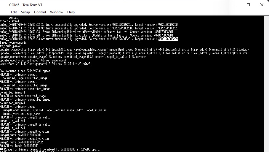
Flashing a new rootfs via serial
If you wish to change the firmware via serial, we recommend using the web app: Web Serial Flash
- Connecting the molex-serial adapter and the serial to the computer as indicated in Root Procedure
- Open Tera Term (or any other programme capable of connecting to the serial terminal)
- Connect the SFP stick to the SFP molex, from the terminal you will have 5 seconds to lock the bootloader by doing a simple CTRL+C. Now upload the firmware image of the new rootfs partition to the stick with the command
FALCON => loady 0x80800000At this point it will appear:
-
From the teratem menu do
FILE→TRANSFER→YMODEM→SEND→[mtd2.bin]. It will start uploading the file at a speed of about 3-4 KBps. Now you will have to wait more than half an hour for the upload to complete. -
Once finished, the image loaded on the stick must also be saved to the corresponding system partition (the first of the 2) with the commands
FALCON => setenv committed_image 0
FALCON => setenv image0_is_valid 1
FALCON => saveenv
FALCON => sf probe 0 && sf erase C0000 740000 && sf write 80800000 C0000 740000 && reset
FALCON => sf probe 0 && sf erase 800000 800000 && sf write 80800000 800000 800000 && reset EEPROM (I2C slave simulated EEPROM)
The Huawei MA5671A does not have a physical EEPROM, the Falcon SOC emulates an EEPROM by exposing it on the I2C interface as required by the SFF-8472 specification.
On the I2C interface there will be two memories of 256 bytes each at the addresses 1010000X (A0h) and 1010001X (A2h), however in reality the memory available from the emulated EEPROM will be 640 bytes each but only the first 256 bytes will be exposed in the I2C interface.
The Huawei MA5671A stores the content of the emulated EEPROM in U-Boot env variables to restore it after a reboot:
EEPROM0 (A0h)stored in U-Boot env variablesfp_a0_low_128EEPROM1 (A2h)stored in U-Boot env variablesfp_a2_info
EEPROM0 layout
| address | size | name | default value | description |
|---|---|---|---|---|
| BASE ID FIELDS (SFF-8472) | ||||
| 0 | 1 | Identifier | 0x03 (SFP) | Type of transceiver |
| 1 | 1 | Ext identifier | 0x04 (MOD_DEF 4) | Additional information about the transceiver |
| 2 | 1 | Connector | 0x01 (SC) | Type of media connector |
| 3-10 | 8 | Transceiver | 0x00 0x00 0x00 0x00 0x00 0x00 0x00 0x00 | Code for optical compatibility |
| 11 | 1 | Encoding | 0x03 (NRZ) | High speed serial encoding algorithm |
| 12 | 1 | Signaling Rate, Nominal | 0x0C (1.244Gbps) | Nominal signaling rate |
| 13 | 1 | Rate Identifier | 0x00 (Not used) | Type of rate select functionality |
| 14 | 1 | Length (SMF,km) | 0x14 (20 km) | Link length supported for single-mode fiber, units of km |
| 15 | 1 | Length (SMF) | 0xC8 (200 x 100m) | Link length supported for single-mode fiber, units of 100 m |
| 16 | 1 | Length (50 um, OM2) | 0x00 (No support) | Link length supported for 50 um OM2 fiber, units of 10 m |
| 17 | 1 | Length (62.5 um, OM1) | 0x00 (No support) | Link length supported for 62.5 um OM1 fiber, units of 10 m |
| 18 | 1 | Length copper cable | 0x00 (No support) | Link length supported for copper or direct attach cable, units of m |
| 19 | 1 | Length (50 um, OM3) | 0x00 (No support) | Link length supported for 50 um OM3 fiber, units of 10 m |
| 20-35 | 16 | Vendor name | 0x48 0x55 0x41 0x57 0x45 0x49 0x20 0x20 0x20 0x20 0x20 0x20 0x20 0x20 0x20 0x20 (HUAWEI) | SFP vendor name (ASCII) |
| 36 | 1 | Transceiver | 0x00 (No support) | Code for optical compatibility |
| 37-39 | 3 | Vendor OUI | 0x00 0x00 0x00 (No specified) | SFP vendor IEEE company ID |
| 40-55 | 16 | Vendor PN | 0x4D 0x41 0x35 0x36 0x37 0x31 0x41 0x20 0x20 0x20 0x20 0x20 0x20 0x20 0x20 0x20 (MA5671A) | Part number provided by SFP vendor (ASCII) |
| 56-59 | 4 | Vendor rev | 0x30 0x30 0x30 0x30 (0000) | Revision level for part number provided by vendor (ASCII) |
| 60-61 | 2 | Wavelength | 0x05 0x1E (1310nm TX) | Laser wavelength |
| 62 | 1 | Fibre Channel Speed 2 | 0x00 (No support) | Transceiver’s Fibre Channel speed capabilities |
| 63 | 1 | CC_BASE | Check code for Base ID Fields (addresses 0 to 62) | |
| EXTENDED ID FIELDS (SFF-8472) | ||||
| 64-65 | 2 | Options | 0x00 0x1A (TX DISABLE, TX FAULT, RX LOS) | Indicates which optional transceiver signals are implemented |
| 66 | 1 | Signaling Rate, max | 0x00 (No specified) | Upper signaling rate margin, units of % |
| 67 | 1 | Signaling Rate, min | 0x00 (No specified) | Lower signaling rate margin, units of % |
| 68-83 | 16 | Vendor SN | Unique in each SFP | Serial number provided by vendor (ASCII) |
| 84-91 | 8 | Date code | Unique in each SFP | Vendor’s manufacturing date code |
| 92 | 1 | Diagnostic Monitoring Type | 0x68 (Digital diagnostic, Internally calibrated, Received average power type) | Indicates which type of diagnostic monitoring is implemented |
| 93 | 1 | Enhanced Options | 0xE0 (Alarm/warning flags, soft TX_DISABLE control, soft TX_FAULT monitoring) | Indicates which optional enhanced features are implemented |
| 94 | 1 | SFF-8472 Compliance | 0x03 (Rev 10.2 of SFF-8472) | Indicates which revision of SFF-8472 the transceiver complies with |
| 95 | 1 | CC_EXT | Check code for the Extended ID Fields (addresses 64 to 94) | |
| VENDOR SPECIFIC FIELDS | ||||
| 96-127 | 32 | Vendor data | Not sure if it’s unique or not | Vendor specifc data (ASCII) |
| 128-255 | 128 | Reserved | 0x00 0x00 0x00... | Reserved |
| EXTRA EEPROM FIELDS | Not exposed to I2C interface | |||
| 256-639 | 384 | Reserved | 0x00 0x00 0x00... | Reserved |
EEPROM1 layout
| address | size | name | default value | description |
|---|---|---|---|---|
| DIAGNOSTIC AND CONTROL FIELDS | ||||
| 0-1 | 2 | Temp High Alarm | 0x5F 0x00 (95℃) | Value expressed in two’s complement |
| 2-3 | 2 | Temp Low Alarm | 0xCE 0x00 (-50℃) | Value expressed in two’s complement |
| 4-5 | 2 | Temp High Warning | 0x5A 0x00 (90℃) | Value expressed in two’s complement |
| 6-7 | 2 | Temp Low Warning | 0xD3 0x00 (-45℃) | Value expressed in two’s complement |
| 8-9 | 2 | Voltage High Alarm | 0x8C 0xA0 (3.6V) | Value expressed in volt subunits1 |
| 10-11 | 2 | Voltage Low Alarm | 0x75 0x30 (3.0V) | Value expressed in volt subunits1 |
| 12-13 | 2 | Voltage High Warning | 0x88 0xB8 (3.5V) | Value expressed in volt subunits1 |
| 14-15 | 2 | Voltage Low Warning | 0x79 0x18 (3.1V) | Value expressed in volt subunits1 |
| 16-17 | 2 | Bias High Alarm | 0xAF 0xC8 (90mA) | Value expressed in milliampere subunits1 |
| 18-19 | 2 | Bias Low Alarm | 0x00 0x00 (0mA) | Value expressed in milliampere subunits1 |
| 20-21 | 2 | Bias High Warning | 0x88 0xB8 (70mA) | Value expressed in milliampere subunits1 |
| 22-23 | 2 | Bias Low Warning | 0x00 0x00 (0mA) | Value expressed in milliampere subunits1 |
| 24-25 | 2 | TX Power High Alarm | 0x9B 0x82 (6dBm) | Value expressed in watts subunits1 |
| 26-27 | 2 | TX Power Low Alarm | 0x22 0xD0 (-1dBm) | Value expressed in watts subunits1 |
| 28-29 | 2 | TX Power High Warning | 0x7B 0x86 (5dBm) | Value expressed in watts subunits1 |
| 30-31 | 2 | TX Power Low Warning | 0x2B 0xD4 (0dBm) | Value expressed in watts subunits1 |
| 32-33 | 2 | RX Power High Alarm | 0x09 0xCF (-6dBm) | Value expressed in watts subunits1 |
| 34-35 | 2 | RX Power Low Alarm | 0x00 0x0D (-29dBm) | Value expressed in watts subunits1 |
| 36-37 | 2 | RX Power High Warning | 0x07 0xCB (-7dBm) | Value expressed in watts subunits1 |
| 38-39 | 2 | RX Power Low Warning | 0x00 0x10 (-28dBm) | Value expressed in watts subunits1 |
| 40-45 | 6 | MAC address | Unique in each SFP | Contains the mac address of the SFP, it could also be empty |
| 46-55 | 10 | Reserved | 0x00 0x00 0x00... | Reserved |
| 56-59 | 4 | RX_PWR(4) Calibration | 0x00 0x00 0x00 0x00 | 4th order RSSI calibration coefficient |
| 60-63 | 4 | RX_PWR(3) Calibration | 0x00 0x00 0x00 0x00 | 3rd order RSSI calibration coefficient |
| 64-67 | 4 | RX_PWR(2) Calibration | 0x00 0x00 0x00 0x00 | 2nd order RSSI calibration coefficient |
| 68-71 | 4 | RX_PWR(1) Calibration | 0x3F 0x80 0x00 0x00 | 1st order RSSI calibration coefficient |
| 72-75 | 4 | RX_PWR(0) Calibration | 0x00 0x00 0x00 0x00 | 0th order RSSI calibration coefficient |
| 76-77 | 2 | TX_I(Slope) Calibration | 0x01 0x00 | Slope for Bias calibration |
| 78-79 | 2 | TX_I(Offset) Calibration | 0x00 0x00 | Offset for Bias calibration |
| 80-81 | 2 | TX_PWR(Slope) Calibration | 0x01 0x00 | Slope for TX Power calibration |
| 82-83 | 2 | TX_PWR(Offset) Calibration | 0x00 0x00 | Offset for TX Power calibration |
| 84-85 | 2 | T(Slope) Calibration | 0x01 0x00 | Slope for Temperature calibration |
| 86-87 | 2 | T(Offset) Calibration | 0x00 0x00 | Offset for Temperature calibration, in units of 256ths °C |
| 88-89 | 2 | V(Slope) Calibration | 0x01 0x00 | Slope for VCC calibration |
| 90-91 | 2 | V(Offset) Calibration | 0x00 0x00 | Offset for VCC calibration |
| 92-94 | 3 | Reserved | 0x00 0x00 0x00 | Reserved |
| 95 | 1 | CC_DMI | Check code for Base Diagnostic Fields (addresses 0 to 94) | |
| 96 | 1 | Temperature MSB | Internally measured module temperature | |
| 97 | 1 | Temperature LSB | ||
| 98 | 1 | Vcc MSB | Internally measured supply voltage in transceiver | |
| 99 | 1 | Vcc LSB | ||
| 100 | 1 | TX Bias MSB | Internally measured TX Bias Current | |
| 101 | 1 | TX Bias LSB | ||
| 102 | 1 | TX Power MSB | Measured TX output power | |
| 103 | 1 | TX Power LSB | ||
| 104 | 1 | RX Power MSB | Measured RX input power | |
| 105 | 1 | RX Power LSB | ||
| 106-109 | 4 | Optional Diagnostics | 0xFF 0xFF 0xFF 0xFF (No support) | Monitor Data for Optional Laser temperature and TEC current |
| 110 | 1 | Status/Control | 0x00 (No support) | Optional Status and Control Bits |
| 111 | 1 | Reserved | 0x00 | Reserved |
| 112-113 | 2 | Alarm Flags | Supported | Diagnostic Alarm Flag Status Bits |
| 114 | 1 | Tx Input EQ control | 0xFF (No support) | Tx Input equalization level control |
| 115 | 1 | Rx Out Emphasis control | 0xFF (No support) | Rx Output emphasis level control |
| 116-117 | 2 | Warning Flags | Supported | Diagnostic Warning Flag Status Bits |
| 118-119 | 2 | Ext Status/Control | 0x00 0x00 (No support) | Extended module control and status bytes |
| GENERAL USE FIELDS | ||||
| 120-126 | 7 | Vendor Specific | 0x70 0x00 0x00 0x00 0x00 0x00 0x00 | Vendor specific memory addresses |
| 127 | 1 | Table Select | 0x00 | Optional Page Select |
| USER WRITABLE EEPROM | ||||
| 128-190 | 63 | Reserved | 0xFF 0xFF 0xFF... | Reserved |
| 191-214 | 24 | GPON LOID or PLOAM | Depends on the configuration of the SFP | GPON Logical ONU ID or PLOAM, depends on GPON LOID/PLOAM switch |
| 215-231 | 17 | GPON LPWD | Depends on the configuration of the SFP | GPON Logical Password |
| 232 | 1 | GPON LOID/PLOAM switch | Depends on the configuration of the SFP | 0x01 to enable LOID, 0x02 to enable PLOAM |
| 233-240 | 8 | GPON SN | Unique in each SFP | GPON Serial Number (ME 256) |
| 241-247 | 7 | Reserved | 0xFF 0xFF 0xFF... | Reserved |
| 248-255 | 8 | Vendor Control | 0xFF 0xFF 0xFF... (Not used) | Vendor specific control functions |
| EXTRA EEPROM FIELDS | Not exposed to I2C interface | |||
| 256-511 | 256 | Unknown vendor specific | Probably not used in current SFPs | |
| 512-531 | 20 | GPON Equipment ID | GPON Equipment ID (ME 257), may not work in some firmwares | |
| 532-535 | 4 | GPON Vendor ID | GPON Vendor ID (ME 256 and more), may not work in some firmware | |
| 536-639 | 104 | Reserved | Reserved |
Miscellaneous Links
- Support MA5671A SFP GPON - OpenWRT forum
- u boot lantiq falcon - GitHub
- Custom Firmware - right.com.cn
- Come avere i 2.5 Gbps su un unico dispositivo senza il Fastgate - fibra.click Forum
- GPON SFP Tools
- Come avere i 2.5 Gbps su un unico dispositivo senza il Fastgate
- La fibre Orange à 2Gbps, sur un routeur MikroTik 10Gbps CCR2004, via un ONT SFP+
- Bypassing the HH3K up to 2.5Gbps using a BCM57810S NIC
- General setting of lantiq
- HUAWEI MA5671A SFP module
- Usage GPON module SFP in Spain
- Tech Info Depot Wiki
Table of contents
- Carlito Firmware for Huawei MA5671A
- FS Modded Firmware for Huawei MA5671A and FS.com GPON-ONU-34-20BI
- Huawei Rooted Firmware for Huawei MA5671A
- List of Root Procedure for Huawei MA5671A
- Root Procedure for Huawei MA5671A (V3)
- Root Procedure for Huawei MA5671A (flash firmware)
- SourcePhotonics Firmware for Huawei MA5671A