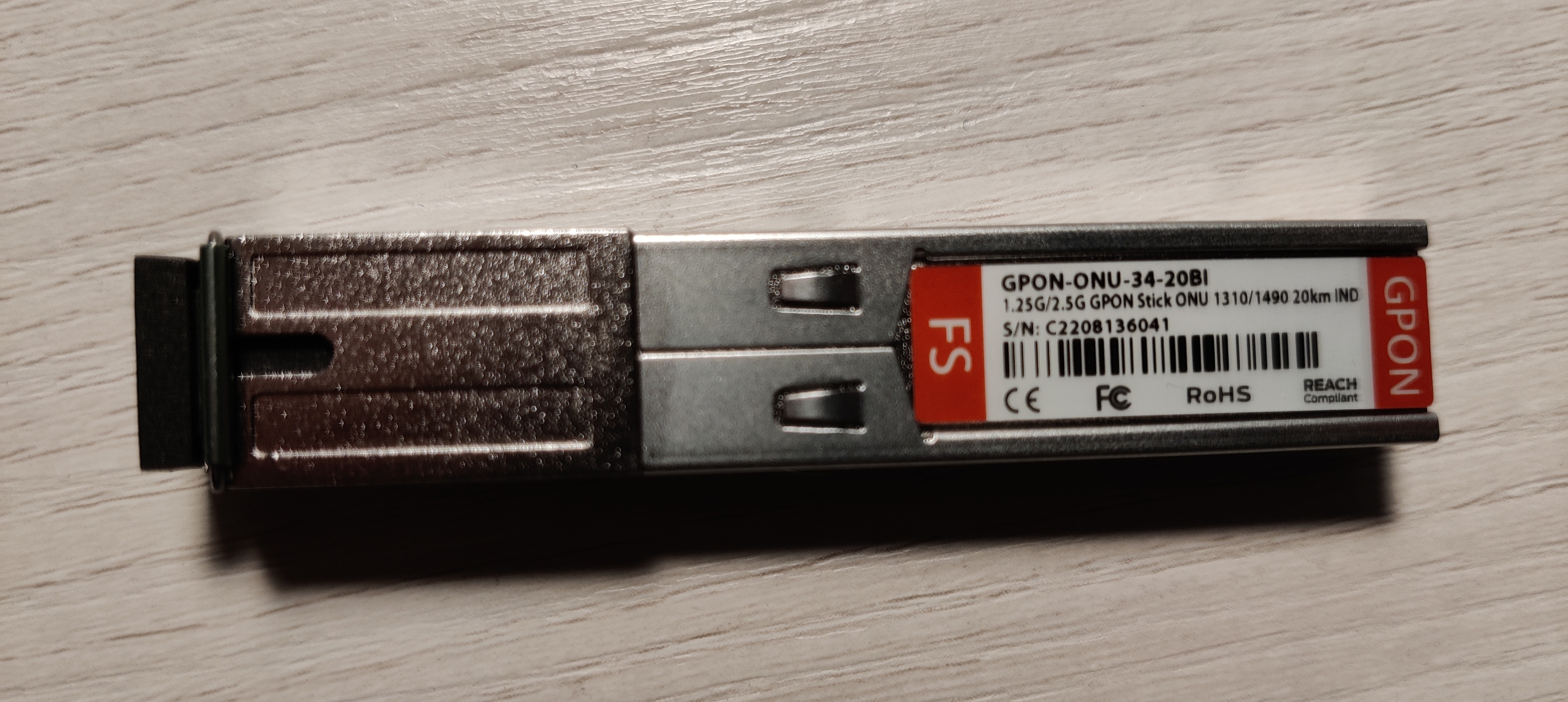
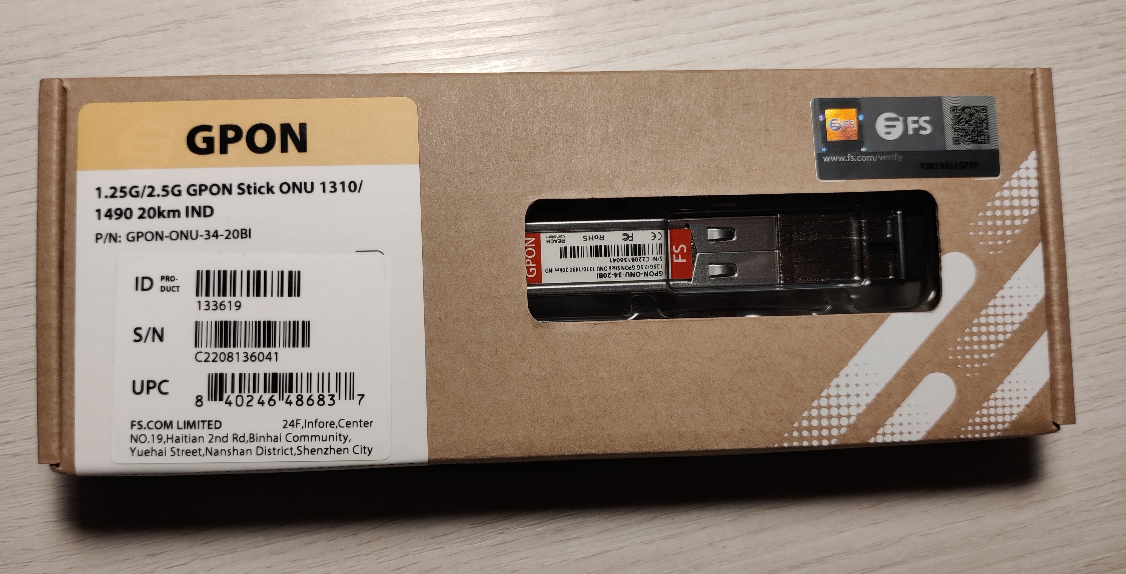
FS.com GPON ONU Stick with MAC (GPON-ONU-34-20BI)
Also sold as: SourcePhotonics SPS-34-24T-HP-TDFO
Hardware Specifications
| Vendor/Brand | FS.com |
| Model | GPON-ONU-34-20BI |
| ODM | SourcePhotonics |
| ODM Product Code | SPS-34-24T-HP-TDFO |
| Chipset | Lantiq PEB98035 |
| CPU | MIPS 34Kc interAptiv |
| CPU Clock | 400MHz |
| Flash | 16 MB |
| RAM | 64 MB |
| Bootloader | U-Boot 2011.12-lantiq-gpon-1.2.24 |
| System | OpenWRT 14.07_ltq (Kernel 3.10.49) |
| Load addr | 0x80800000 |
| HSGMII | Yes |
| Optics | SC/APC |
| IP address | 192.168.1.10 |
| Web Gui | |
| SSH | ✅ user ONTUSER, password 7sp!lwUBz1 |
| Telnet | |
| Serial | ✅ on SFP |
| Serial baud | 115200 |
| Serial encoding | 8-N-1 |
| Form Factor | miniONT SFP |
Possible clones
- SourcePhotonics SPS-34-24T-HP-TDFO
Firmware is interchangeable with:
- Huawei MA5671A
- Nokia G-010S-P
- Hilink HL23446
- Dasan H650SFP
- DpOptics D23446
- Photonics SPS-34-24T-HP-TDFO
Serial
The stick has a TTL 3.3v UART console (configured as 115200 8-N-1) that can be accessed from the SFP connector.
| USB TTL(UART) Adapter | SFP 20pins Molex connector |
|---|---|
| 3.3V | pin #15 and #16 |
| TX | pin #2 |
| RX | pin #7 |
| GND | pin #14 |
List of software versions
- 6BA1896SPLQA13 (Dec 16 2016)
- 6BA1896SPLQA41
- 6BA1896SPLQA42 (Sep 18 2021)
List of partitions
Partition layouts change depending on which image is booted, in particular:
When booting image0:
mtd2 ---> image0 (linux)
mtd5 --> image1
mtd3 --> rootfs
mtd4 --> rootfs_data
When booting image0:
mtd2 ---> image0
mtd3 --> image1 (linux)
mtd4 --> rootfs
mtd5 --> rootfs_data
For more info XPONos partition layout.
When booting from image0
| dev | size | erasesize | name |
|---|---|---|---|
| mtd0 | 00040000 | 00010000 | “uboot” |
| mtd1 | 00080000 | 00010000 | “uboot_env” |
| mtd2 | 00740000 | 00010000 | “linux” |
| mtd3 | 0061eedc | 00010000 | “rootfs” |
| mtd4 | 00370000 | 00010000 | “rootfs_data” |
| mtd5 | 00800000 | 00010000 | “image1” |
When booting from image1
| dev | size | erasesize | name |
|---|---|---|---|
| mtd0 | 00040000 | 00010000 | “uboot” |
| mtd1 | 00080000 | 00010000 | “uboot_env” |
| mtd2 | 00740000 | 00010000 | “image0” |
| mtd3 | 00800000 | 00010000 | “linux” |
| mtd4 | 006d8077 | 00010000 | “rootfs” |
| mtd5 | 00410000 | 00010000 | “rootfs_data” |
List of firmwares and files
- 6BA1896SPLQA13 MTD0/U-Boot md5hash: 992b31a67c644aa68cf7f9caf956b1f9
- 6BA1896SPLQA13 MTD2/Image0 md5hash: 5d46a9acc3c5ba8710887aa32b82aeb4
- 6BA1896SPLQA42 MTD0/U-Boot md5hash: 992b31a67c644aa68cf7f9caf956b1f9
- 6BA1896SPLQA42 MTD2/Image0 md5hash: 04533554bb0c8b997697fbc048159002
Unlock the device
Bootloader unlock from shell
fw_setenv bootdelay 5
fw_setenv asc0 0
fw_setenv preboot "gpio set 3;gpio input 2;gpio input 105;gpio input 106;gpio input 107;gpio input 108"
Emergency bootloader unlock via TTL serial
If for some reason you are in the situation where you do not have a bootable firmware on your SFP stick you can do an emergency unlock via TTL serial.
To perform the emergency unlock, the following hardware is required:
- TTL-USB adapter,
- SFP adapter to connect the TTL-USB cables to the SFP stick.
The electrical connections are the same as those of the Huawei MA5671A; see the Huawei root guide for accurate details on how to connect the TTL-USB to the SFP adapter.
When you are ready with everything plugged in you need to press the button below. A window will open to execute the emergency unlock.
GPON ONU status
Getting the operational status of the ONU
onu ploamsg
Querying a particular OMCI ME
omci_pipe.sh meg MIB_IDX ME_IN
Where MIB_IDX is the MIB ID and the ME_IN is the ME instance number
Getting/Setting Speed LAN Mode
To get the LAN Mode:
onu lanpsg 0
The link_status variable tells the current speed
Value (for sgmii_mode and link_status) | Speed |
|---|---|
| 3 | 1 Gbps / SGMII with auto-neg on |
| 4 | 1 Gbps / SGMII with auto-neg off |
| 5 | 2.5 Gbps / HSGMII with auto-neg on |
To change the default lan mode value you can use fw_setenv sgmii_mode. The firmware already has the value set to 5 by default and there should not be any need to change it.
GPON/OMCI settings
Setting ONU GPON Serial Number
set_serial_number ABCD12345678
Or:
sfp_i2c -i8 -s "ABCD12345678"
Getting ONU GPON Serial Number
fw_printenv | grep nSerial
Or:
sfp_i2c -g
Setting ONU GPON PLOAM password
sfp_i2c -i11 -s "1234567890"
Setting ONU GPON LOID and LOID password
sfp_i2c -i9 -s "1234567890"
sfp_i2c -i10 -s "password01"
Setting OMCI equipment ID (ME 257)
sfp_i2c -i6 -s "YOUR_EQUIPMENT_ID"
Setting OMCI Vendor ID (ME 256)
sfp_i2c -i7 -s "YOUR_VENDOR_ID"
Setting OMCI hardware version (ME 256)
sed 's/256 0 HWTC 0000000000000/256 0 HWTC YOUR_ONU_VERSION/' /rom/etc/mibs/data_1g_8q.ini > /etc/mibs/data_1g_8q.ini
Restoring the default ONU hardware version (ME 256)
cat /rom/etc/mibs/data_1g_8q.ini > /etc/mibs/data_1g_8q.ini
Setting OMCI software version (ME 7)
6BA1896SPLQA42 The image version normally can’t be changed because it is hard-coded into the /opt/lantiq/bin/omcid binary, so the binary has to be modified with the following hex patch which removes the hardcoded version.
< 000084c0: 9a43 931f f760 d840 9b64 f760 d864 1a00  .C...`.@.d.`.d..
< 000084d0: 1acf 6500 1a20 2268 940a 2205 b468 1a00  ..e.. "h.."..h..
---
> 000084c0: 9a43 931f f760 d840 9b64 f760 d864 6500  .C...`.@.d.`.de.
> 000084d0: 6500 6500 1a20 2268 940a 2205 b468 1a00  e.e.. "h.."..h..
md5sum /opt/lantiq/bin/omcid has the correct checksum 7e97163e24c9cb39439589c65b438168 This is the patch, encoded in base64
QlNESUZGNDA1AAAAAAAAAD4AAAAAAAAA2C8JAAAAAABCWmg5MUFZJlNZYqnvBwAACFBSQWAAAMAA
AAgAQCAAMQwIIwjImgDOdMvi7kinChIMVT3g4EJaaDkxQVkmU1lrJSbUAACFTAjAACAAAAiCAAAI
IABQYAFKQ01INxUgd6Soj2JURm8pUR8XckU4UJBrJSbUQlpoORdyRThQkAAAAAA=
Save it on your computer (not on the stick) as omcid_patch.base64, then run:
base64 -d omcid_patch.base64 > omcid.bspatch
bspatch <your_original_omcid> omcid omcid.bspatch
After patching the resulting patched omcid should have an md5 checksum of 525139425009c4138e92766645dad7d0. If that is also correct, continue by making a backup copy of your original omcid on the stick.
cd /opt/lantiq/bin
cp omcid omcid.original
Now, SCP has to be used to copy the modified omcid binary in /opt/lantiq/bin/omcid. Before restarting the stick and applying changes, make sure omcid has its execution bit set, then reboot the stick and change the image version with the following command:
chmod ugo+x /opt/lantiq/bin/omcid
Is also a good time to set the image0/image1_version: crashes have been reported if they are not set correctly before reboot.
fw_setenv image0_version YOUR_IMAGE0_VERSION
fw_setenv image1_version YOUR_IMAGE1_VERSION
Now the stick can be rebooted.
omcid can rewrite the two variables when run in its non-patched state. After reboot, double check the set values are still correct. Advanced settings
Setting data_1g_8q_us1280_ds512.ini OMCI MIB file for 2500 Mbps profiles
6BA1896SPLQA42 /etc/mibs/data_1g_8q_us1280_ds512.ini instead of /etc/mibs/data_1g_8q.ini The MIB file data_1g_8q_us1280_ds512.ini is very useful to avoid performance problems in situations where 2500 Mbps speed profiles are used. To enable it, run this command:
fw_setenv mib_file data_1g_8q_us1280_ds512.ini
Setting custom OMCI MIB file
/etc/mibs/data_1g_8q.ini Copy the MIB file to /etc/mibs, then run this command:
fw_setenv mib_file YOUR_MIB_FILENAME
Setting management MAC
uci set network.lct.macaddr=00:06:B5:07:D6:04
uci set network.host.macaddr=00:06:B5:07:D8:04
uci commit network.lct.macaddr=00:06:B5:07:D6:04
uci commit network.host.macaddr=00:06:B5:07:D8:04
Setting management IP
fw_setenv ipaddr 192.168.20.60
fw_setenv gatewayip 192.168.20.1
Rebooting the ONU
reboot
Disable RX_LOS status
6BA1896SPLQA42 Some switches/routers (e.g. Mikrotik) do not allow access to the magament interface without the fiber being connected because the SFP reports RX_LOS status It is possible to fix this by modifying the mod_optic.ko driver to spoof non RX_LOS status by setting PIN 8 (RX_LOS) to be always low.
This is the change to be made, in hex format:
< 00013740: 2404 0003 2405 0001 0c00 0000 ac43 0980  $...$........C..
---
> 00013740: 2404 0003 2405 0000 0c00 0000 ac43 0980  $...$........C..
md5sum /lib/modules/3.10.49/mod_optic.ko has the correct checksum 7c718c3410c4120fe98fa7a9a5c6c407 This is the patch, encoded in base64:
QlNESUZGNDA2AAAAAAAAADYAAAAAAAAAXEEFAAAAAABCWmg5MUFZJlNZ5TTrjgAAB+ZARjAEACAA
AARAACAAMQZMQRppiFkgKGTeXi7kinChIcpp1xxCWmg5MUFZJlNZcaVLvQABOOCAwAAAAQAIAAig
ACClRgZoMhUf9JKbgIk3hdyRThQkHGlS70BCWmg5F3JFOFCQAAAAAA==
Save it on your computer (not on the stick) as mod_optic.base64, then run:
base64 -d mod_optic.base64 > mod_optic.bspatch
bspatch <your_original_mod_optic.ko> mod_optic.ko mod_optic.bspatch
After patching the resulting mod_optic.ko should have an md5 checksum of e14a5a70b023873853afe920870f076e. If that is also correct, continue by making a backup copy of your original mod_optic.ko on the stick.
cd /lib/modules/3.10.49/
cp mod_optic.ko mod_optic.ko.original
Now use SCP to copy the modified mod_optic.ko kernel module in /lib/modules/3.10.49/mod_optic.ko.
TX Fault / Serial
The stick will remain in a perpetual “TX Fault” state as the same SFP pin is used for both serial and TX Fault signaling. If this causes you issues (normally it shouldn’t), you can issue the commands below to disable it. Note that this will disable both the TX Fault signal and Serial on the stick after boot.
fw_setenv asc0 1
fw_setenv preboot "gpio set 3;gpio input 100;gpio input 105;gpio input 106;gpio input 107;gpio input 108"
In case you need to re-enable it, issue the following commands from the bootloader (FALCON)
FALCON => setenv asc0 0
FALCON => saveenv
SFP EEPROM settings
Reading all EEPROM
sfp_i2c -r
Getting Firmware version
strings /opt/lantiq/bin/omcid | grep ^software_Version | awk -F[=,] '{print $2}'
Getting Firmware build time
strings /opt/lantiq/bin/omcid | grep compiled
EEPROM (I2C slave simulated EEPROM)
The FS GPON-ONU-34-20BI stick does not have a physical EEPROM, the Falcon SOC emulates an EEPROM by exposing it on the I2C interface as required by the SFF-8472 specification.
On the I2C interface, two memories of 256 bytes each will be available at the addresses 1010000X (A0h) and 1010001X (A2h), however the actual available memory from the emulated EEPROM will be 640 bytes each, but only the first 256 bytes will be exposed in the I2C interface.
The FS stick stores the content of the emulated EEPROM in U-Boot env variables to restore it after a reboot:
EEPROM0 (A0h)stored in U-Boot env variablesfp_a0_low_128EEPROM1 (A2h)stored in U-Boot env variablesfp_a2_info
EEPROM0 layout
| address | size | name | default value | description |
|---|---|---|---|---|
| BASE ID FIELDS (SFF-8472) | ||||
| 0 | 1 | Identifier | 0x03 (SFP) | Type of transceiver |
| 1 | 1 | Ext identifier | 0x04 (MOD_DEF 4) | Additional information about the transceiver |
| 2 | 1 | Connector | 0x01 (SC) | Type of media connector |
| 3-10 | 8 | Transceiver | 0x00 0x00 0x00 0x00 0x00 0x00 0x00 0x00 | Code for optical compatibility |
| 11 | 1 | Encoding | 0x03 (NRZ) | High speed serial encoding algorithm |
| 12 | 1 | Signaling Rate, Nominal | 0x0C (1.244Gbps) | Nominal signaling rate |
| 13 | 1 | Rate Identifier | 0x00 (Not used) | Type of rate select functionality |
| 14 | 1 | Length (SMF,km) | 0x14 (20 km) | Link length supported for single-mode fiber, units of km |
| 15 | 1 | Length (SMF) | 0xC8 (200 x 100m) | Link length supported for single-mode fiber, units of 100 m |
| 16 | 1 | Length (50 um, OM2) | 0x00 (No support) | Link length supported for 50 um OM2 fiber, units of 10 m |
| 17 | 1 | Length (62.5 um, OM1) | 0x00 (No support) | Link length supported for 62.5 um OM1 fiber, units of 10 m |
| 18 | 1 | Length copper cable | 0x00 (No support) | Link length supported for copper or direct attach cable, units of m |
| 19 | 1 | Length (50 um, OM3) | 0x00 (No support) | Link length supported for 50 um OM3 fiber, units of 10 m |
| 20-35 | 16 | Vendor name | 0x46 0x53 0x20 0x20 0x20 0x20 0x20 0x20 0x20 0x20 0x20 0x20 0x20 0x20 0x20 0x20 (FS) | SFP vendor name (ASCII) |
| 36 | 1 | Transceiver | 0x00 (No support) | Code for optical compatibility |
| 37-39 | 3 | Vendor OUI | 0x00 0x00 0x00 (No specified) | SFP vendor IEEE company ID |
| 40-55 | 16 | Vendor PN | 0x47 0x50 0x4F 0x4E 0x2D 0x4F 0x4E 0x55 0x2D 0x33 0x34 0x2D 0x32 0x30 0x42 0x49 (GPON-ONU-34-20BI) | Part number provided by SFP vendor (ASCII) |
| 56-59 | 4 | Vendor rev | 0x30 0x31 0x20 0x20 (01) | Revision level for part number provided by vendor (ASCII) |
| 60-61 | 2 | Wavelength | 0x05 0x1E (1310nm TX) | Laser wavelength |
| 62 | 1 | Fibre Channel Speed 2 | 0x00 (No support) | Transceiver’s Fibre Channel speed capabilities |
| 63 | 1 | CC_BASE | Check code for Base ID Fields (addresses 0 to 62) | |
| EXTENDED ID FIELDS (SFF-8472) | ||||
| 64-65 | 2 | Options | 0x00 0x1A (TX DISABLE, TX FAULT, RX LOS) | Indicates which optional transceiver signals are implemented |
| 66 | 1 | Signaling Rate, max | 0x00 (No specified) | Upper signaling rate margin, units of % |
| 67 | 1 | Signaling Rate, min | 0x00 (No specified) | Lower signaling rate margin, units of % |
| 68-83 | 16 | Vendor SN | Unique in each SFP | Serial number provided by vendor (ASCII) |
| 84-91 | 8 | Date code | Unique in each SFP | Vendor’s manufacturing date code |
| 92 | 1 | Diagnostic Monitoring Type | 0x68 (Digital diagnostic, Internally calibrated, Received average power type) | Indicates which type of diagnostic monitoring is implemented |
| 93 | 1 | Enhanced Options | 0xF0 (Alarm/warning flags, soft TX_DISABLE control, soft TX_FAULT monitoring, soft RX_LOS monitoring) | Indicates which optional enhanced features are implemented |
| 94 | 1 | SFF-8472 Compliance | 0x05 (Rev 11.0 of SFF-8472) | Indicates which revision of SFF-8472 the transceiver complies with |
| 95 | 1 | CC_EXT | Check code for the Extended ID Fields (addresses 64 to 94) | |
| VENDOR SPECIFIC FIELDS | ||||
| 96-127 | 32 | Vendor data | 0x20 0x20 0x20... (Not used) | Vendor specifc data (ASCII) |
| 128-255 | 128 | Reserved | 0x00 0x00 0x00... | Reserved |
| EXTRA EEPROM FIELDS | Not exposed to I2C interface | |||
| 256-639 | 384 | Reserved | 0x00 0x00 0x00... | Reserved |
EEPROM1 layout
| address | size | name | default value | description |
|---|---|---|---|---|
| DIAGNOSTIC AND CONTROL FIELDS | ||||
| 0-1 | 2 | Temp High Alarm | 0x5F 0x00 (95℃) | Value expressed in two’s complement |
| 2-3 | 2 | Temp Low Alarm | 0xCE 0x00 (-50℃) | Value expressed in two’s complement |
| 4-5 | 2 | Temp High Warning | 0x5A 0x00 (90℃) | Value expressed in two’s complement |
| 6-7 | 2 | Temp Low Warning | 0xD3 0x00 (-45℃) | Value expressed in two’s complement |
| 8-9 | 2 | Voltage High Alarm | 0x8C 0xA0 (3.6V) | Value expressed in volt subunits1 |
| 10-11 | 2 | Voltage Low Alarm | 0x75 0x30 (3.0V) | Value expressed in volt subunits1 |
| 12-13 | 2 | Voltage High Warning | 0x88 0xB8 (3.5V) | Value expressed in volt subunits1 |
| 14-15 | 2 | Voltage Low Warning | 0x79 0x18 (3.1V) | Value expressed in milliampere subunits1 |
| 16-17 | 2 | Bias High Alarm | 0xAF 0xC8 (90mA) | Value expressed in milliampere subunits1 |
| 18-19 | 2 | Bias Low Alarm | 0x00 0x00 (0mA) | Value expressed in milliampere subunits1 |
| 20-21 | 2 | Bias High Warning | 0x88 0xB8 (70mA) | Value expressed in milliampere subunits1 |
| 22-23 | 2 | Bias Low Warning | 0x00 0x00 (0mA) | Value expressed in milliampere subunits1 |
| 24-25 | 2 | TX Power High Alarm | 0xF6 0x77 (8dBm) | Value expressed in watts subunits1 |
| 26-27 | 2 | TX Power Low Alarm | 0x15 0xF7 (-2.5dBm) | Value expressed in watts subunits1 |
| 28-29 | 2 | TX Power High Warning | 0xC3 0xC6 (7dBm) | Value expressed in watts subunits1 |
| 30-31 | 2 | TX Power Low Warning | 0x1B 0xA7 (-1.5dBm) | Value expressed in watts subunits1 |
| 32-33 | 2 | RX Power High Alarm | 0x0C 0x5A (-5dBm) | Value expressed in watts subunits1 |
| 34-35 | 2 | RX Power Low Alarm | 0x00 0x08 (-31dBm) | Value expressed in watts subunits1 |
| 36-37 | 2 | RX Power High Warning | 0x09 0xCF (-6dBm) | Value expressed in watts subunits1 |
| 38-39 | 2 | RX Power Low Warning | 0x00 0x0A (-30dBm) | Value expressed in watts subunits1 |
| 40-45 | 6 | MAC address | Unique in each SFP | Contains the mac address of the SFP, it could also be empty |
| 46-55 | 10 | Reserved | 0x00 0x00 0x00... | Reserved |
| 56-59 | 4 | RX_PWR(4) Calibration | 0x00 0x00 0x00 0x00 | 4th order RSSI calibration coefficient |
| 60-63 | 4 | RX_PWR(3) Calibration | 0x00 0x00 0x00 0x00 | 3rd order RSSI calibration coefficient |
| 64-67 | 4 | RX_PWR(2) Calibration | 0x00 0x00 0x00 0x00 | 2nd order RSSI calibration coefficient |
| 68-71 | 4 | RX_PWR(1) Calibration | 0x3F 0x80 0x00 0x00 | 1st order RSSI calibration coefficient |
| 72-75 | 4 | RX_PWR(0) Calibration | 0x00 0x00 0x00 0x00 | 0th order RSSI calibration coefficient |
| 76-77 | 2 | TX_I(Slope) Calibration | 0x01 0x00 | Slope for Bias calibration |
| 78-79 | 2 | TX_I(Offset) Calibration | 0x00 0x00 | Offset for Bias calibration |
| 80-81 | 2 | TX_PWR(Slope) Calibration | 0x01 0x00 | Slope for TX Power calibration |
| 82-83 | 2 | TX_PWR(Offset) Calibration | 0x00 0x00 | Offset for TX Power calibration |
| 84-85 | 2 | T(Slope) Calibration | 0x01 0x00 | Slope for Temperature calibration |
| 86-87 | 2 | T(Offset) Calibration | 0x00 0x00 | Offset for Temperature calibration, in units of 256ths °C |
| 88-89 | 2 | V(Slope) Calibration | 0x01 0x00 | Slope for VCC calibration |
| 90-91 | 2 | V(Offset) Calibration | 0x00 0x00 | Offset for VCC calibration |
| 92-94 | 3 | Reserved | 0x00 0x00 0x00 | Reserved |
| 95 | 1 | CC_DMI | Check code for Base Diagnostic Fields (addresses 0 to 94) | |
| 96 | 1 | Temperature MSB | Internally measured module temperature | |
| 97 | 1 | Temperature LSB | ||
| 98 | 1 | Vcc MSB | Internally measured supply voltage in transceiver | |
| 99 | 1 | Vcc LSB | ||
| 100 | 1 | TX Bias MSB | Internally measured TX Bias Current | |
| 101 | 1 | TX Bias LSB | ||
| 102 | 1 | TX Power MSB | Measured TX output power | |
| 103 | 1 | TX Power LSB | ||
| 104 | 1 | RX Power MSB | Measured RX input power | |
| 105 | 1 | RX Power LSB | ||
| 106-109 | 4 | Optional Diagnostics | 0xFF 0xFF 0xFF 0xFF (No support) | Monitor Data for Optional Laser temperature and TEC current |
| 110 | 1 | Status/Control | 0x82 (Soft TX disable, disable laser, digital TX fault, digital RX LOS, power&data ready) | Optional Status and Control Bits |
| 111 | 1 | Reserved | 0x00 | Reserved |
| 112-113 | 2 | Alarm Flags | Supported | Diagnostic Alarm Flag Status Bits |
| 114 | 1 | Tx Input EQ control | 0xFF (No support) | Tx Input equalization level control |
| 115 | 1 | Rx Out Emphasis control | 0xFF (No support) | Rx Output emphasis level control |
| 116-117 | 2 | Warning Flags | Supported | Diagnostic Warning Flag Status Bits |
| 118-119 | 2 | Ext Status/Control | 0x00 0x00 (No support) | Extended module control and status bytes |
| GENERAL USE FIELDS | ||||
| 120-126 | 7 | Vendor Specific | 0x70 0x00 0x00 0x00 0x00 0x00 0x00 | Vendor specific memory addresses |
| 127 | 1 | Table Select | 0x00 | Optional Page Select |
| USER WRITABLE EEPROM | ||||
| 128-190 | 63 | Reserved | 0xFF 0xFF 0xFF... | Reserved |
| 191-214 | 24 | GPON LOID or PLOAM | Depends on the configuration of the SFP | GPON Logical ONU ID or PLOAM, depends on GPON LOID/PLOAM switch |
| 215-231 | 17 | GPON LPWD | Depends on the configuration of the SFP | GPON Logical Password |
| 232 | 1 | GPON LOID/PLOAM switch | Depends on the configuration of the SFP | 0x01 to enable LOID, 0x02 to enable PLOAM |
| 233-240 | 8 | GPON SN | Unique in each SFP | GPON Serial Number (ME 256) |
| 241-247 | 7 | Reserved | 0xFF 0xFF 0xFF... | Reserved |
| 248-255 | 8 | Vendor Control | 0xFF 0xFF 0xFF... (Not used) | Vendor specific control functions |
| EXTRA EEPROM FIELDS | Not exposed to I2C interface | |||
| 256-511 | 256 | Unknown vendor specific | Probably not used in current SFPs | |
| 512-531 | 20 | GPON Equipment ID | GPON Equipment ID (ME 257), may not work in some firmwares | |
| 532-535 | 4 | GPON Vendor ID | GPON Vendor ID (ME 256 and more), may not work in some firmware | |
| 536-639 | 104 | Reserved | Reserved |
Miscellaneous Links
- FS.com
- General setting of lantiq
- Usage GPON module SFP in Spain
- SourcePhotonics SPS-34-24T-HP-TDFO Datasheet