Zyxel PMG3000-D20B
Hardware Specifications
| Vendor/Brand | Zyxel |
| Model | PMG3000-D20B |
| ODM | T&W |
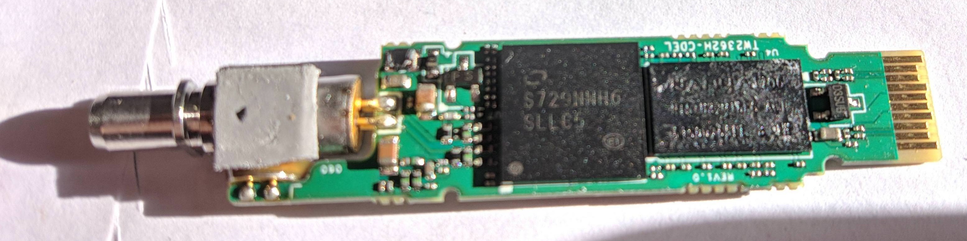
| ODM Product Code | TW2362H-CDEL |
| Chipset | Lantiq PEB98035 |
| Flash | 8 MB |
| RAM | 64 MB |
| CPU | MIPS 34Kc interAptiv |
| CPU Clock | 400MHz |
| System | eCoS |
| HSGMII | Yes |
| Optics | SC/APC |
| IP address | 10.10.1.1 |
| Web Gui | ✅ username admin or guest, password 1234 or guest |
| SSH | ✅ username admin, password admin |
| Telnet | |
| Serial | ✅ |
| Serial baud | 115200 |
| Serial encoding | 8-N-1 |
| Form Factor | miniONT SFP |
Once you access the stick via ssh you will be presented with a second tier login. The credentials to access the zyxel shell are: username: twmanu , password: twmanu. From the Zyxel shell you can move to a standard Linux shell using the linuxshell command
Serial
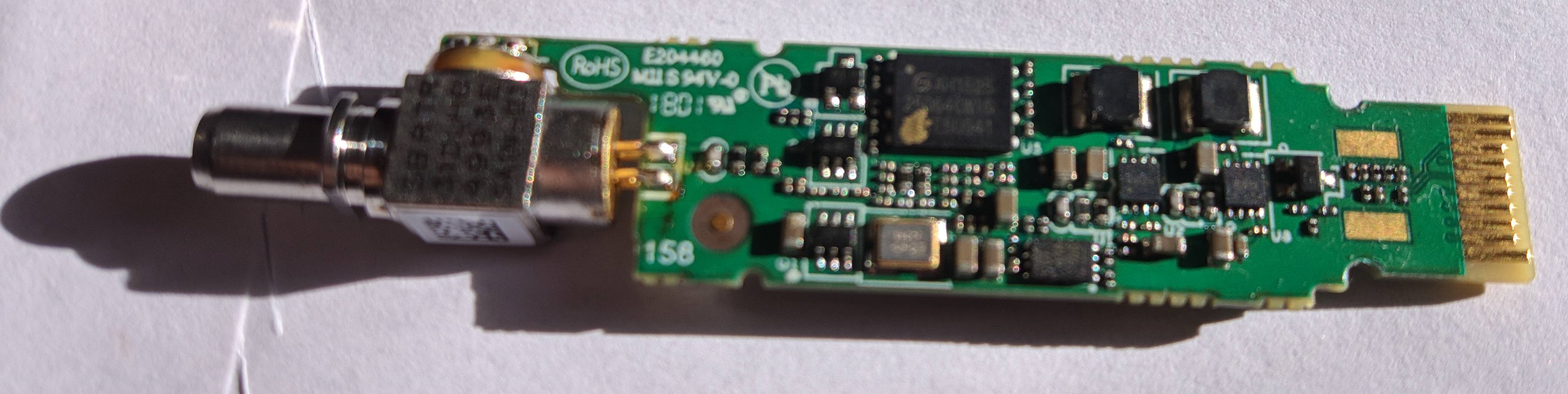
The stick has a TTL 3.3v UART console (configured as 115200 8-N-1) that can be accessed from the top surface. It’s near the SFP header. TX, RX and ground pads need to be connected to a USB2TTL adapter supporting 3V3 logic.

Firmware is interchangeable with:
List of software versions
- V1.00(ABVJ.0)b3s (2020)
- V1.00(ABVJ.0)b3i (2020)
- V1.00(ABVJ.0)b3v
- V2.50(ABVJ.0)b1b (2022)
- V2.50(ABVJ.1)b1d (2023)
List of partitions
| dev | size | erasesize | name |
|---|---|---|---|
| mtd0 | 00060000 | 00010000 | “Boot” |
| mtd1 | 00010000 | 00010000 | “Env” |
| mtd2 | 00390000 | 00010000 | “ImageA” |
| mtd3 | 00390000 | 00010000 | “ImageB” |
| mtd4 | 00060000 | 00010000 | “Config” |
| mtd5 | 00010000 | 00010000 | “SECTION_EGIS” |
| mtd6 | 00250000 | 00010000 | “rootfs” |
| mtd7 | 00020000 | 00010000 | “rootfs_data” |
This stick supports dual boot, as visible from the presence of ImageA and ImageB, which contain the rootfs.
Useful files and binaries
Useful files
/var/config/ont.sys- Used to customize various settings on the stick. If you don’t have it you can copy the stock one from /ont.sys
General Settings and Useful Commands
GPON ONU status
Getting the operational status of the ONU
To check the connection status, use the following command:
linuxshell
onu ploamsg
curr_state=5 for O5 state, curr_state=1 for all other operational states.
Getting Speed LAN Mode
This SFP has HSGMII enabled by default: link_status=5 for HSGMII 2.5Gbit, link_status=4 for SGMII 1Gbit:
linuxshell
onu lanpsg 0
Setting Speed LAN Mode
hal
set speed 2.5g mode full
Querying a particular OMCI ME
Query via OMCI ME Class Name:
omci
show me classname OmciClassName (e.g Ont2g)
Query via OMCI ME ID:
omci
show me classid OmciClassId (e.g 7)
GPON/OMCI settings
Setting ONU GPON Serial Number
manufactory
set sn ALCLf0f0f0f0
exit
hal
set sn ALCLf0f0f0f0
Do not worry if one of the two commands results missing, the change is still applied with just one of them.
Setting ONU GPON PLOAM password
This can be done easily via the web UI. To do it via the shell use:
hal
set password PLOAMPASS
Setting OMCI software version (ME 7)
Edit /var/config/ont.sys via vi directly on the stick itself. The file is CRLF terminated, one entry per line. The entries for the software version are:
SW_VER0:0xabcdef
SW_VER1:0xabcedf
Setting OMCI hardware version (ME 256)
manufactory
set hardware version 3FE49165BFAA01
If the above command is missing you can edit /var/config/ont.sys via vi directly on the stick itself. The file is CRLF terminated, one entry per line. The entry for the hardware version is:
ONTG_VER:0x463630303556362e300000000000
The hardware version must be encoded in hex format and right padded to 28 characters with 0 (excluding the starting 0x) to avoid any spurious values.
Setting OMCI equipment ID (ME 257)
manufactory
set equipment id MYEQUIPMENTID
exit
omci
equipment id MYEQUIPMENTID
If any of the above commands is missing you can edit /var/config/ont.sys via vi directly on the stick itself. The file is CRLF terminated, one entry per line. The entry for the equipment id is:
ONTG_EQID:0x463630303556362E30000000000000000000000
The equipment id must be encoded in hex format and right padded to 39 characters with 0 (excluding the starting 0x) to avoid any spurious values.
Advanced settings
Resetting Web GUI admin credentials
Under certain circumstances, the Web GUI admin credentials might get changed from the default admin/1234 combination. To restore the default combination try following this method.
Creating a new rootfs
The stick has a tricky image packing method, fortunately it has been reverse engineered. A script to help you create a custom rootfs can be found here: https://github.com/hack-gpon/zyxel-pmg-3000-mod-kit
Flashing a new rootfs
- Transfer the new mtd on the stick via tftp:
linuxshell tftp -gr mtd2.mod.bin TFTP_SERVER_IP - Flash it on the standby partition. You can use
systemand thenshow actimageto get the current active image. Check/proc/mtdfor the right mtds. Usually: - if the currect active image is A, mtd2 is in use
- If the current active image is B, mtd3 is in use
linuxshell mtd -e /dev/mtd2 write /tmp/mtd2.mod.bin /dev/mtd2 - Switch to the new image:
system set actimage a - Reboot the ONT:
system
reboot
EEPROM (I2C slave simulated EEPROM)
The Zyxel PMG3000-D20B does not have a physical EEPROM, the Falcon SOC emulates an EEPROM by exposing it on the I2C interface as required by the SFF-8472 specification.
On the I2C interface, two memories of 256 bytes each will be available at the addresses 1010000X (A0h) and 1010001X (A2h).
The Zyxel PMG3000-D20B stores the content of the emulated EEPROM1 (A2h) in /tmp/config/sfp_eeprom1 to restore it after a reboot.
EEPROM0 layout
| address | size | name | default value | description |
|---|---|---|---|---|
| BASE ID FIELDS (SFF-8472) | ||||
| 0 | 1 | Identifier | 0x03 (SFP) | Type of transceiver |
| 1 | 1 | Ext identifier | 0x04 (MOD_DEF 4) | Additional information about the transceiver |
| 2 | 1 | Connector | 0x01 (SC) | Type of media connector |
| 3-10 | 8 | Transceiver | 0x04 0x40 0x00 0x02 0x12 0x10 0x00 0x80 (1X LX, 1310TX SMF, 1000BASE-LX, 1200 Mbps) | Code for optical compatibility |
| 11 | 1 | Encoding | 0x03 (8B/10B) | High speed serial encoding algorithm |
| 12 | 1 | Signaling Rate, Nominal | 0x0C (1Gbps) | Nominal signaling rate |
| 13 | 1 | Rate Identifier | 0x00 (Not used) | Type of rate select functionality |
| 14 | 1 | Length (SMF,km) | 0x14 (20 km) | Link length supported for single-mode fiber, units of km |
| 15 | 1 | Length (SMF) | 0xC8 (200 x 100m) | Link length supported for single-mode fiber, units of 100 m |
| 16 | 1 | Length (50 um, OM2) | 0xFF (No support) | Link length supported for 50 um OM2 fiber, units of 10 m |
| 17 | 1 | Length (62.5 um, OM1) | 0xFF (No support) | Link length supported for 62.5 um OM1 fiber, units of 10 m |
| 18 | 1 | Length copper cable | 0x00 (No support) | Link length supported for copper or direct attach cable, units of m |
| 19 | 1 | Length (50 um, OM3) | 0xFF (No support) | Link length supported for 50 um OM3 fiber, units of 10 m |
| 20-35 | 16 | Vendor name | 0x4C 0x61 0x6E 0x74 0x69 0x71 0x20 0x20 0x20 0x20 0x20 0x20 0x20 0x20 0x20 0x20 (Lantiq) | SFP vendor name (ASCII) |
| 36 | 1 | Transceiver | 0x00 (No support) | Code for optical compatibility |
| 37-39 | 3 | Vendor OUI | 0x00 0x1C 0xAD | SFP vendor IEEE company ID |
| 40-55 | 16 | Vendor PN | 0x50 0x61 0x72 0x74 0x20 0x4E 0x75 0x6D 0x62 0x65 0x72 0x20 0x20 0x20 0x20 0x20 (Part Number) | Part number provided by SFP vendor (ASCII) |
| 56-59 | 4 | Vendor rev | 0x30 0x30 0x30 0x30 (0000) | Revision level for part number provided by vendor (ASCII) |
| 60-61 | 2 | Wavelength | 0x05 0x1E (1310nm TX) | Laser wavelength |
| 62 | 1 | Fibre Channel Speed 2 | 0xFF (No support) | Transceiver’s Fibre Channel speed capabilities |
| 63 | 1 | CC_BASE | Check code for Base ID Fields (addresses 0 to 62) | |
| EXTENDED ID FIELDS (SFF-8472) | ||||
| 64-65 | 2 | Options | 0x00 0x1A (TX DISABLE, TX FAULT, RX LOS) | Indicates which optional transceiver signals are implemented |
| 66 | 1 | Signaling Rate, max | 0x00 (No specified) | Upper signaling rate margin, units of % |
| 67 | 1 | Signaling Rate, min | 0x00 (No specified) | Lower signaling rate margin, units of % |
| 68-83 | 16 | Vendor SN | 0x6E 0x6F 0x20 0x73 0x65 0x72 0x69 0x61 0x6C 0x20 0x6E 0x75 0x6D 0x62 0x65 0x72 (no serial number) | Serial number provided by vendor (ASCII) |
| 84-91 | 8 | Date code | 0x31 0x33 0x30 0x31 0x30 0x31 0x20 0x20 (130101) | Vendor’s manufacturing date code |
| 92 | 1 | Diagnostic Monitoring Type | 0x6C (Digital diagnostic, Internally calibrated, Received average power type, address change) | Indicates which type of diagnostic monitoring is implemented |
| 93 | 1 | Enhanced Options | 0xF0 (Alarm/warning flags, soft TX_DISABLE control, soft TX_FAULT monitoring, soft RX_LOS monitoring) | Indicates which optional enhanced features are implemented |
| 94 | 1 | SFF-8472 Compliance | 0x05 (Rev 11.0 of SFF-8472) | Indicates which revision of SFF-8472 the transceiver complies with |
| 95 | 1 | CC_EXT | Check code for the Extended ID Fields (addresses 64 to 94) | |
| VENDOR SPECIFIC FIELDS | ||||
| 96-127 | 32 | Vendor data | 0x20 0x20 0x20... (Not used) | Vendor specifc data (ASCII) |
| 128-255 | 128 | Reserved | 0x00 0x00 0x00... | Reserved |
EEPROM1 layout
| address | size | name | default value | description |
|---|---|---|---|---|
| DIAGNOSTIC AND CONTROL FIELDS | ||||
| 0-1 | 2 | Temp High Alarm | 0x64 0x00 (100℃) | Value expressed in two’s complement |
| 2-3 | 2 | Temp Low Alarm | 0xCE 0x00 (-50℃) | Value expressed in two’s complement |
| 4-5 | 2 | Temp High Warning | 0x55 0x00 (85℃) | Value expressed in two’s complement |
| 6-7 | 2 | Temp Low Warning | 0xD8 0x00 (-40℃) | Value expressed in two’s complement |
| 8-9 | 2 | Voltage High Alarm | 0x8C 0xA0 (3.6V) | Value expressed in volt subunits[^subunit] |
| 10-11 | 2 | Voltage Low Alarm | 0x75 0x30 (3.0V) | Value expressed in volt subunits[^subunit] |
| 12-13 | 2 | Voltage High Warning | 0x88 0xB8 (3.5V) | Value expressed in volt subunits[^subunit] |
| 14-15 | 2 | Voltage Low Warning | 0x79 0x18 (3.1V) | Value expressed in volt subunits[^subunit] |
| 16-17 | 2 | Bias High Alarm | 0xAF 0xC8 (90mA) | Value expressed in milliampere subunits[^subunit] |
| 18-19 | 2 | Bias Low Alarm | 0x00 0x00 (0mA) | Value expressed in milliampere subunits[^subunit] |
| 20-21 | 2 | Bias High Warning | 0x88 0xB8 (70mA) | Value expressed in milliampere subunits[^subunit] |
| 22-23 | 2 | Bias Low Warning | 0x00 0x00 (0mA) | Value expressed in milliampere subunits[^subunit] |
| 24-25 | 2 | TX Power High Alarm | 0x7B 0x86 (5dBm) | Value expressed in watts subunits[^subunit] |
| 26-27 | 2 | TX Power Low Alarm | 0x27 0x10 (0dBm) | Value expressed in watts subunits[^subunit] |
| 28-29 | 2 | TX Power High Warning | 0x6E 0x17 (4dBm) | Value expressed in watts subunits[^subunit] |
| 30-31 | 2 | TX Power Low Warning | 0x2B 0xD4 (0.1dBm) | Value expressed in watts subunits[^subunit] |
| 32-33 | 2 | RX Power High Alarm | 0x07 0xCB (-7dBm) | Value expressed in watts subunits[^subunit] |
| 34-35 | 2 | RX Power Low Alarm | 0x00 0x0F (-28dBm) | Value expressed in watts subunits[^subunit] |
| 36-37 | 2 | RX Power High Warning | 0x06 0x30 (-8dBm) | Value expressed in watts subunits[^subunit] |
| 38-39 | 2 | RX Power Low Warning | 0x00 0x14 (-27dBm) | Value expressed in watts subunits[^subunit] |
| 40-55 | 16 | Reserved | 0x00 0x00 0x00... | Contains the mac address of the SFP, it could also be empty |
| 56-59 | 4 | RX_PWR(4) Calibration | 0x00 0x00 0x00 0x00 | 4th order RSSI calibration coefficient |
| 60-63 | 4 | RX_PWR(3) Calibration | 0x00 0x00 0x00 0x00 | 3rd order RSSI calibration coefficient |
| 64-67 | 4 | RX_PWR(2) Calibration | 0x00 0x00 0x00 0x00 | 2nd order RSSI calibration coefficient |
| 68-71 | 4 | RX_PWR(1) Calibration | 0x00 0x00 0x00 0x00 | 1st order RSSI calibration coefficient |
| 72-75 | 4 | RX_PWR(0) Calibration | 0x00 0x00 0x00 0x00 | 0th order RSSI calibration coefficient |
| 76-77 | 2 | TX_I(Slope) Calibration | 0x00 0x00 | Slope for Bias calibration |
| 78-79 | 2 | TX_I(Offset) Calibration | 0x00 0x00 | Offset for Bias calibration |
| 80-81 | 2 | TX_PWR(Slope) Calibration | 0x00 0x00 | Slope for TX Power calibration |
| 82-83 | 2 | TX_PWR(Offset) Calibration | 0x00 0x00 | Offset for TX Power calibration |
| 84-85 | 2 | T(Slope) Calibration | 0x00 0x00 | Slope for Temperature calibration |
| 86-87 | 2 | T(Offset) Calibration | 0x00 0x00 | Offset for Temperature calibration, in units of 256ths °C |
| 88-89 | 2 | V(Slope) Calibration | 0x00 0x00 | Slope for VCC calibration |
| 90-91 | 2 | V(Offset) Calibration | 0x00 0x00 | Offset for VCC calibration |
| 92-94 | 3 | Reserved | 0x00 0x00 0x00 | Reserved |
| 95 | 1 | CC_DMI | Check code for Base Diagnostic Fields (addresses 0 to 94) | |
| 96 | 1 | Temperature MSB | Internally measured module temperature | |
| 97 | 1 | Temperature LSB | ||
| 98 | 1 | Vcc MSB | Internally measured supply voltage in transceiver | |
| 99 | 1 | Vcc LSB | ||
| 100 | 1 | TX Bias MSB | Internally measured TX Bias Current | |
| 101 | 1 | TX Bias LSB | ||
| 102 | 1 | TX Power MSB | Measured TX output power | |
| 103 | 1 | TX Power LSB | ||
| 104 | 1 | RX Power MSB | Measured RX input power | |
| 105 | 1 | RX Power LSB | ||
| 106-109 | 4 | Optional Diagnostics | 0x00 0x00 0x00 0x00 (No support) | Monitor Data for Optional Laser temperature and TEC current |
| 110 | 1 | Status/Control | 0x02 (Digital RX LOS) | Optional Status and Control Bits |
| 111 | 1 | Reserved | 0x00 | Reserved |
| 112-113 | 2 | Alarm Flags | Supported | Diagnostic Alarm Flag Status Bits |
| 114 | 1 | Tx Input EQ control | 0x00 (No support) | Tx Input equalization level control |
| 115 | 1 | Rx Out Emphasis control | 0x00 (No support) | Rx Output emphasis level control |
| 116-117 | 2 | Warning Flags | Supported | Diagnostic Warning Flag Status Bits |
| 118-119 | 2 | Ext Status/Control | 0x00 0x00 (No support) | Extended module control and status bytes |
| GENERAL USE FIELDS | ||||
| 120-126 | 7 | Vendor Specific | 0x00 0x00 0x00 0x00 0x00 0x00 0x00 | Vendor specific memory addresses |
| 127 | 1 | Table Select | 0x00 | Optional Page Select |
| USER WRITABLE EEPROM | ||||
| 128-232 | 105 | Reserved | 0x00 0x00 0x00... | Reserved |
| 233-240 | 8 | GPON SN | Unique in each SFP | GPON Serial Number (ME 256) |
| 241-247 | 7 | Reserved | 0x00 0x00 0x00... | Reserved |
| 248-255 | 8 | Vendor Control | 0x00 0x00 0x00... (Not used) | Vendor specific control functions |
Known Bugs
- Works with Broadcom BCM57810S only after solder mod
- Issue on IPv6 discovery. Not certain whether it is a edge case of a particular ISP or not
- Some sticks have a custom password
- On V2.5 the Lantiq SDK has been updated from 6.4.2 to 7.5.1, breaking upload performance
Miscellaneous Links
- Zyxel gpon-sfp
- Zyxel PMG-3000 mod kit
- Rollback SFP Zyxel con il W3 HUB per risolvere il problema dell’upload cappato